News Center
LATEST NEWS
- 013.3V-24V 8A Isolation Flip-Flop Latch Switch Module Bistable Single Button LED Relay Solenoid Valve
- 028CH 433M Bidirectional IO Controller Point-to-Point Feedback Remote Controller Relay Switch Module for Garage Security PTZ Camera
- 03Surface Assembly Technology: Overview of SMT
- 04IFA 2025
- 05Sample Show
- 06PCBA Automation Production Line Exploration and Outlook

Email: sales@hyzk-electronics.com
Phone: 0086 18682384515
Address: 3rd floor, Building 6, 30 Fortress Road, Gongming Street, Guangming District, Shenzhen 518106
Industry articles
HomeIndustry articlesDetails
Surface Assembly Technology: Overview of SMT
Publish: 2025-07-23 10:24:32 View: 12201.1. What is SMT technology?
Surface Mounted Technology (SMT) is also known as surface mounting technology. It refers to the automatic assembly technology
that directly installs and welding chip components at designated locations on printed circuit boards, as shown in Figure 1-1.
SMT is developed based o+n Through Hole Technology (THT). From a technical perspective, SMT is a complex system project that integrates
components, printed boards, SMT design, assembly process, equipment, materials and inspection technologies. Figure 1-2 shows the surface
assembly technology system. Surface Mount Components (SMC) and Surface Mount Devices (SMD) are the basis of SMT. The substrate is a
structural part for interconnecting components and plays an important role in ensuring the electrical performance and reliability of electronic
assembly. Assembly processes and equipment are tools and means to realize SMT products, determining productivity and quality results.
Inspection technology is an important guarantee for the quality of surface assembly products.
1.2 Basic SMT process
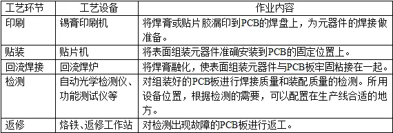
The SMT production process generally includes four links: solder paste printing, patching, reflow soldering, and testing. The SMT production process
can be divided into pure SMT assembly process and mixed assembly process according to the assembly method of components; it can be divided into
single-sided and double-sided processes according to the distribution of circuit board components; it can be divided into solder paste process and red
glue process according to the method of bonding components to the circuit board; it can be divided into reflow soldering process and wave soldering
process according to the welding method. The following mainly introduces the solder paste process and red glue process.
1. Solder paste technology
First print an appropriate amount of solder paste on the solder pad of the printed circuit board, then place the chip components on the specified position
on the surface of the printed circuit board, and finally place the printed circuit board with the mounted components on the conveyor belt of the reflow
soldering equipment. From the inlet of the reflow soldering furnace to the outlet, it takes about 5 minutes to complete the drying, preheating, melting,
cooling and other welding processes.
Table 1-2 Solder paste process
2. Red glue process
First print or drip the micro patch adhesive (red glue) onto the corresponding position of the printed circuit board (note: patch adhesive cannot contaminate
the pads and component ends of the printed circuit board), then place the chip components on the specified position on the surface of the printed circuit board
, so that the printed circuit board with the components mounted is glued and cured.
The cured components are firmly bonded to the printed circuit board, and then the discrete components are inserted, and finally wave soldering is performed
at the same time as the plug-in components.
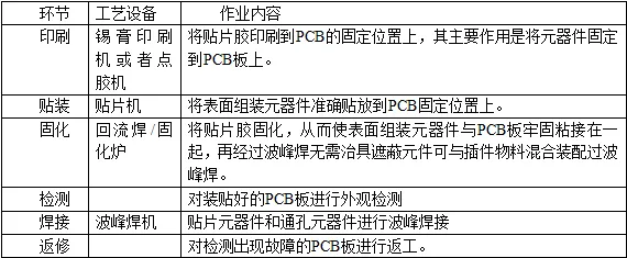
The process flow of red glue is shown in Table 1-3. The mixing (SMD and THT) assembly process usually uses the red glue process.
Table 1-3 Red glue process
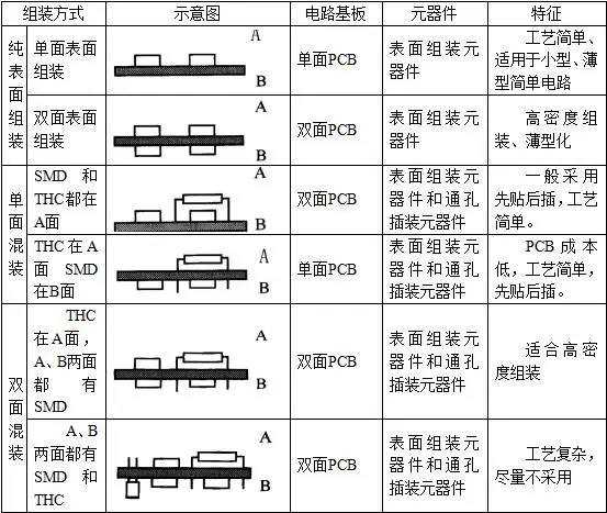
1.3 SMT assembly method
The assembly method and process flow of surface mount technology (SMT) mainly depends on the type of surface assembly (SMA) and the type of
components and assembly equipment conditions. The assembly methods of SMT can be roughly divided into three types: full-surface assembly,
single-sided mixing and double-sided mixing, and a total of 6 assembly methods, as shown in Table 1-4. The assembly method varies for different types
of SMAs. The assembly method can also be different for the same type of SMA.
Table 1-4 SMT assembly method
1.4 SMT equipment
The most basic production process of SMT generally includes three steps: solder paste printing, patch and reflow soldering. Therefore, to form a most basic
SMT production line, it is bound to include equipment that completes the above process steps: plate-mounting machine, printing machine, patch machine and
reflow soldering furnace.
HYZK Have 4 Panasonic SMT LINES!!!
1. Top board desk
(1) Function: Send the PCB boards placed in the material frame to the printing press one by one.
(2) Composition structure: The automatic plate-up machine consists of several parts: frame, plate-up system, plate-up system, deviation adjustment system, roller,
positioning frame, control system, etc.
The advantage of the automatic plate-mounting machine is that it does not require a special equipment foundation and can be placed on hardened flat ground to be used
in conjunction with the plate-loading machine, which reduces the labor intensity of the operators, improves work efficiency, and has the characteristics of flexible operation
and use, reliable performance, and wide application range. Figure 1-6 is an automatic board-mounting machine.
2. Solder paste printing machine
(1) Function: The solder paste printing machine is used to print solder paste or patch adhesive. Its function is to correctly print solder paste or patch adhesive to the corresponding
position of the printed board through the steel mesh plate.
(2) Composition structure: The solder paste printing machine is composed of screen board, scraper, printing workbench, etc.
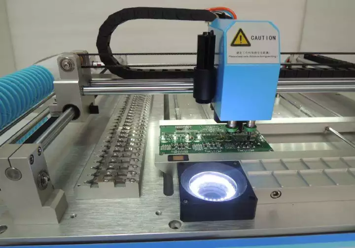
3. SMT patch machine
(1) Function: The function of the patch machine is to take the patch components out of the packaging through the feeder according to the pre-programmed program, and accurately
attach the components to the corresponding position of the printed board.
(2) Composition structure: The patch machine has many brands, diverse structure forms, different models and specifications, and there are certain differences in specific structures,
but the composition structure is basically the same. It is mainly composed of a frame (equipment body), circuit board transmission mechanism and positioning device, patch head and
its motion control system, visual positioning system, power servo system, pneumatic system, computer operating system, etc.
(3) Types of patch machines: Patch machines can be roughly divided into boom arch type, turret type, composite type and large parallel system according to their structural form.
4. Reflow soldering machine
(1) Function: The reflow soldering machine is mainly used for welding various surface assembled components. Its function is to realize mechanical and electrical connection between
the solder ends or pins of the surface assembled components and the printed board pad by remelting the paste solder material pre-distributed to the printed board pad.
The solder for reflow soldering is solder paste. The PCB board with the components is mounted into the reflow soldering equipment. The conveying system drives the circuit board to
pass through each set temperature area in the reflow soldering equipment. The solder paste is dried, preheated, melted, wetted and cooled, and the components are soldered to the
printed board. The core link of reflow soldering is to use an external heating source to heat the solder to melt and flow and wet it again, completing the welding process of the circuit
board.
(2) Composition structure: The overall structure of the hot air reflow soldering furnace is mainly divided into five main parts, including heating zone, cooling zone, gas circulation device
in the furnace, exhaust gas emission device and PCB transmission.
The temperature zone of the reflow soldering furnace usually has four functional zones, namely the preheating zone, the constant temperature zone, the reflow zone (reflow) and the
cooling zone.
Preheating zone: The soldering object is gradually heated from room temperature to an area around 150°C, reducing the temperature difference with the reflow process, and the solvent
in the solder paste is evaporated.
Constant temperature zone: The temperature is maintained at 150-160℃, and the active agent in the solder paste begins to act to remove the oxide layer on the surface of the soldering
object.
Reflow zone: The temperature gradually rises, exceeding the melting point of the solder paste by 30%-40%, and the peak temperature reaches 220-230℃ for more than 10 seconds. The
solder paste is completely melted and wets the solder ends and pads of the components.
Cooling area: The welding object cools down, forms welding joints, and completes welding.
Recommend